Help Desk
Published over 5 years ago. See the latest and most current information on Help Desk.
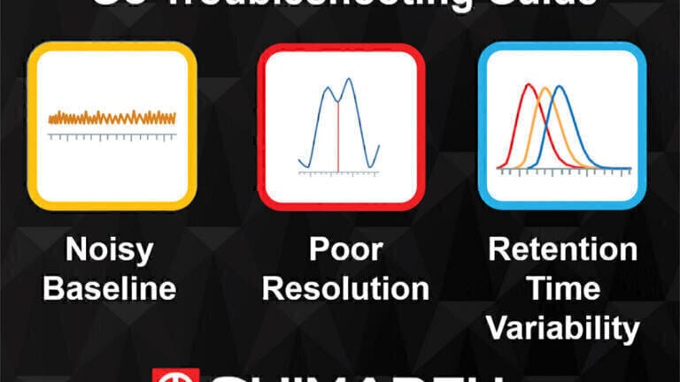
In today’s high-pressure environments, it is important to be able to quickly and accurately troubleshoot any issues that may arise with analytical instrumentation. In part 1 of this article, Shimadzu UK discussed the probable causes of issues with peak shape and how to resolve them. We reviewed effective troubleshooting for abnormal peak shapes in gas chromatography (GC), namely no peaks, fronting or tailing peaks, split peaks, broad peaks, and ghost peaks. In this second part we will continue to build on these skills by looking at solutions for high or unstable baselines, variability in retention time and changes in response.
This troubleshooting knowledge will allow you to pinpoint the cause of an issue, rectify it while minimising downtime, allowing you to get your system back up and running and producing results again.
As with all troubleshooting investigation, a step wise approach is the best, changing only one variable at a time to allow a more focussed systematic process. This will not only help you identify the root cause of the problem but will also allow you to prevent errors from recurring.
Following a methodical process, starting with confirming the reproducibility of an error, and slowly narrowing down the tests to isolate different parts of the instrument to pinpoint where the issue is occurring will allow you to investigate the root cause of the issue.
The advice outlined in this article is very general, and can apply to most gas chromatographic systems, not just Shimadzu models, however processes might vary slightly from system to system, so it is always wise to check guidelines supplied by your provider.
High Baseline
A high baseline can cause issues with integration and sensitivity of target analytes especially those which elute towards the end of the run.
1. Column
a) A high baseline could be a result of improper conditioning of the column. This may be resolved by increasing the conditioning time or temperature.
2. Contamination
a) Over time, contamination from sample matrix can build up on the column, especially at the front end. This can be removed by trimming the column and/or heating the column to its maximum temperature.
b) Impurities in the gases can be a source of contamination. Many systems have in line filters, these can become saturated over time and should be regularly replaced.
c) Contamination from continued use or dirty samples can build up in the injector and detector. These should be cleaned when signs of contamination appear or as part of a routine maintenance regime.
3. Leaks
a) A leak in the system can cause oxidation of the stationary phase which will be seen as column bleed. Check for oxygen leaks across the entire system and replace seals and/or filters as necessary.
b) If the baseline issues persist once the leaks have been fixed, it is possible that the stationary phase has degraded too far, the column will then need to be replaced.
An unstable baseline, such as spiking, excessive noise and drift, can result in poor integration and a loss of sensitivity.
1. Carrier gas leak or contamination
a) Leaks in the flow path of the carrier gas can introduce contamination and variability which can affect the base line. Leak check connections and replace seals if needed.
b) Impurities in the carrier gas can be removed by replacing the supply and/or installing inline filters.
2. Inlet or detector contamination
a) Contamination from continued use or dirty samples can build up in the inlet and on the detector. Routine maintenance should be carried out and parts replaced if they show signs of damage.
3. Column contamination or stationary phase bleed.
a) Contamination on the column or excessive bleed from the stationary phase can affect the base line. The column should be conditioned to reduce the bleed and contamination removed by trimming and rinsing the column.
4. Septum coring or bleed
a) As the septum in the inlet ages, it can become brittle which leads to coring and bleed issues. It should be replaced regularly as part of a maintenance regime.
b) Septum coring can lead to a build-up of particles in the inlet liner. These particles can affect the transfer of the target analytes on to the column and can be a source of contamination. The liner should be checked for particles and replaced if needed.
5. Leak or poor-quality gases.
a) Contamination can be introduced to the system through leaks in the supply or poor-quality gases. All gas lines should be checked for leaks. The purity of the gas supply should be checked to ensure that it is adequate. If necessary, install gas filters to remove moisture and potential contamination.
6. Variable carrier gas or detector gas flows.
a) Variability in the flow of carrier gas or gas to the detector could result in baseline issues such as spiking. This can be resolved by checking the system and fixing any leaks and ensuring the flow and pressure controllers are functioning correctly.
7. Detector not ready.
a) Instability in the baseline could be due to the detector not having enough time to stabilise before the analysis is started. Load the appropriate method and allow enough time for detector temperatures and flows to equilibrate before starting the analysis.
Unexpected changes in the response of the target analytes can affect sensitivity, detection limits and accuracy of quantitation.
1. Sample
A change in the response of the target analyte may be due to issues with the sample. The following should be checked.
a) The sample concentration is as expected.
b) The sample preparation procedure has not changed.
c) The sample has not decomposed and is being analysed within its shelf life.
2. Syringe
a) The syringe may have become partially blocked so is not injecting the required amount of sample on to the system. Check the syringe is working properly and replace it if needed.
b) The autosampler should also be checked to ensure it is functioning correctly.
3. Electronics.
a) A change in the analyte response may be due to the detector settings. Verify the signal settings and adjust them if needed.
4. Dirty or damaged detector.
a) Contamination from continued use or dirty samples can build up on the detector effecting the response of the target analyte. Routine detector maintenance should be carried out and parts replaced if they show signs of damage.
5. Flow/temperature settings wrong or variable
a) If the flow rates and temperatures are not set correctly in the method or are varying, the detector response will be not at its optimal. Verify the flow rates and temperatures are steady, then adjust the settings and/or replace any parts as required.
6. Adsorption/reactivity
a) Contamination in the inlet or front of the column can lead to active sites where the target analytes may be irreversibly absorbed or undergo a chemical change such as decomposition. This can be overcome by removing the source of contamination and using properly deactivated liners and columns.
7. Leaks
a) A leak in any part of the system can affect the amount of sample reaching the detector. Check the system for leaks and repair any connections as needed.
8. Change in sample introduction/injection method.
It is possible that the acquisition method may have been inadvertently changed and over written.
a) Verify what injection technique was initially used and change back to the original technique.
b) Check split ratio is set correctly.
c) Verify that the splitless hold time is correct.
Poor resolution between closely eluting peaks may affect the accurate quantitation of target analytes.
1. Non-selective stationary phase
a) The column may not have the power to resolve the coeluting compounds. The resolution may be improved by choosing a column with a more appropriate stationary phase and column dimensions.
2. Poor efficiency.
a) The method conditions may not be the most efficient for resolving closely eluting compounds. Resolution can be improved by optimising the carrier gas linear velocity and the GC oven program.
3. Sample overload.
a) Injecting too much sample on to the column will reduce the resolution between closely eluting compounds due to the peaks becoming broader. The sample concentration or amount on column can be adjusted by increasing the split ratio or decreasing the injection volume.
Changes in the retention times of target analytes can lead to incorrect identification especially when using non-selective detectors such as a Flame Ionisation Detector (FID).
1. Leaks
a) Leaks in any part of the system can affect the flow of the carrier gas which will cause variability in the retention time of the target analytes. Leak check the inlet and any column connections.
b) Replace parts such as the septa and O-rings if they show signs of wear.
2. Analyte adsorption
a) Increased activity in the inlet and column may result in adsorption of the target analyte. This may affect its transfer to the column and retention on the column. This can be overcome by routine inlet and column maintenance.
b) Use of properly deactivated liners and columns will reduce the potential for active sites.
3. Resolution and integration issues.
a) Adding too much sample can overload the column. This can cause variability in the retention time as well as poor resolution and peak fronting. This can be avoided by diluting the sample, reducing the injection volume and/or increasing the split ratio.
4. Incorrect column/oven temperature program
a) If the column temperature and the oven temperature program are not appropriate for the analysis, there may be variability between runs. Verify that the column temperature and oven temperature program are optimised and set correctly in the acquisition method.
5. Incorrect or variable carrier gas linear velocity.
a) The retention times of the target analytes may be affected by variations in the linear velocity of the carrier gas. Verify the carrier gas linear velocity is optimised and set correctly in the acquisition method.
b) If the instrument is unable to maintain the correct linear velocity, there may be a problem with the flow controller or a leak in the system. Check the system is functioning correctly and repair or replace parts if necessary.
6. Poor control of oven temperature programming.
a) If the oven temperature program in the method is outside the capability of the instrument, it will be unable to accurately maintain the desired temperature. This can cause variability between runs and affect the analyte retention times. This can be resolved by confirming GC oven program falls within instrument specifications.
7. Incorrect oven equilibration time.
a) The oven may not have enough time to stabilise before the run starts. This can be more of an issue if the oven temperature at the start of the run is close to room temperature. This can be overcome by extending the GC oven equilibration time in the acquisition method.
8. Manual injections.
a) When carrying out manual injections, inconsistencies between the injection and pressing the start button can lead to retention time variability. Where possible, standardise the manual injection procedure. Alternatively, using an autosampler will improve reproducibility between injections.
These systems, like all chromatographic techniques, have a list of quite common problems seen by analysts. To aid your troubleshooting, Shimadzu have developed a free troubleshooting guide which discusses these common problems and a list of helpful actions that can be taken. It offers guidance on how to approach certain problems in a methodical, scientific manner. Patience is required and don’t be disheartened if your first course of action doesn’t resolve the issue. Remember that the most obvious answers are usually the correct ones, and there is nothing wrong with checking the basics first.
Finally, if you do have a problem please remember to call your instrument provider. Ultimately, they are here to help, and all want to see instruments up and running as much as you!
The free trouble shooting guide is available from: www.shimadzu.co.uk/form/gc-poster


-(1).jpg)